Which Pixel Pitch and Signal-to-Noise Ratio (SNR) Are Required for Digital Radiography to Detect Fine Porosity in Double-Wall Pipe Welds?
Introduction: When a Tiny Defect Becomes a Big Problem
Jul 27, 2026
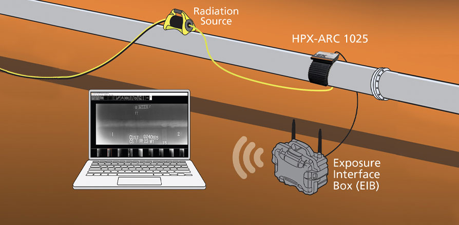
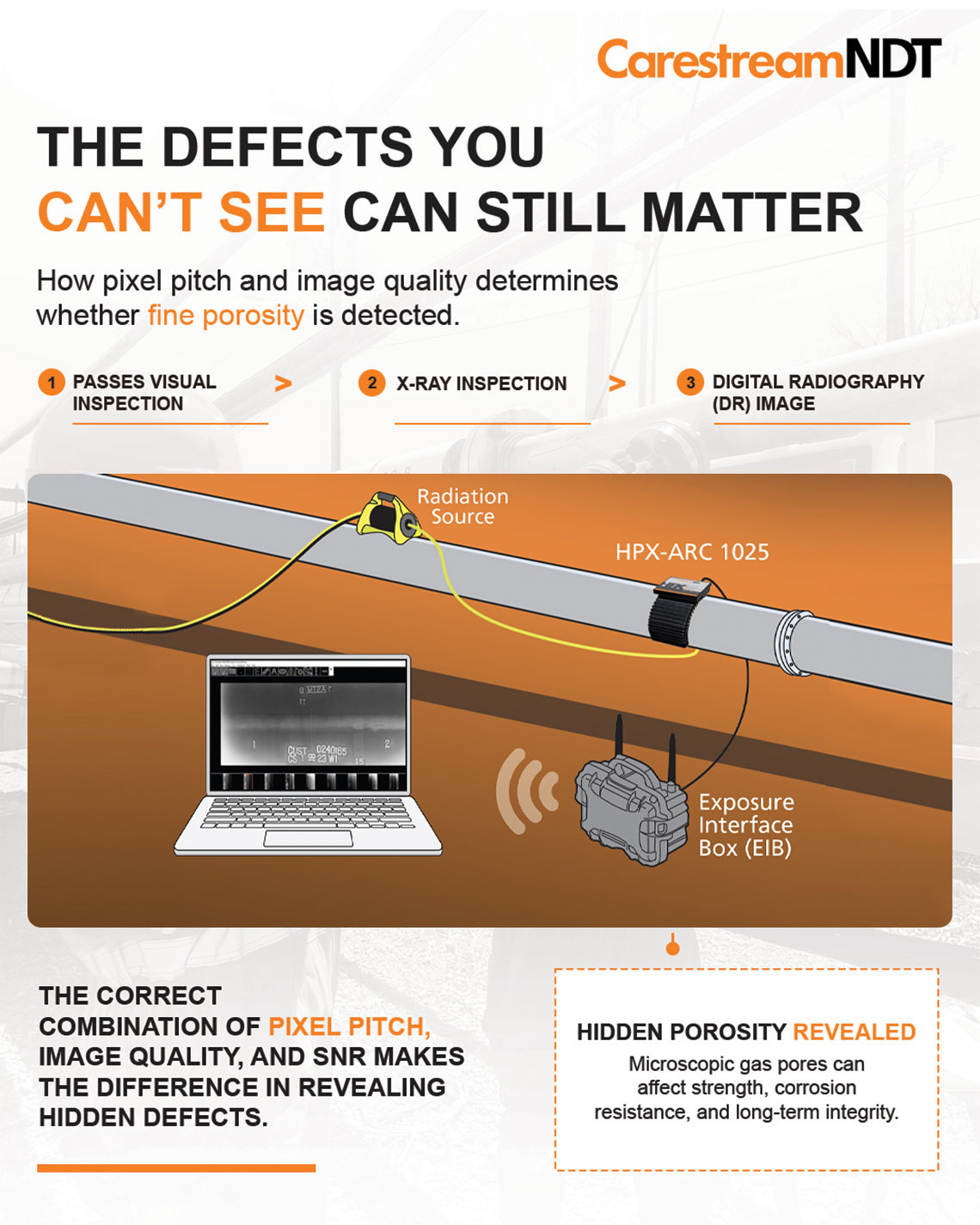
Imagine a newly fabricated pipeline destined for a refinery, offshore platform, or power generation facility. The welds, which join each pipe segment to their adjacents, pass visual inspection and appear flawless to the naked eye. But hidden within the weld, there are often microscopic gas pores—small imperfections that compromise structural integrity and lead to premature failure.
Detecting fine porosity is one of the most demanding challenges in industrial radiography. As the Non-Destructive Testing (NDT) industry continues its transition from Film Radiography to Digital Radiography (DR), inspectors are increasingly asking a set of similar questions:
Which pixel pitch and Signal-to-Noise Ratio (SNR) are necessary to reliably detect fine porosity in double-wall pipe weld inspections?
The answer lies in understanding how image resolution and image quality work together to reveal defects that may be only fractions of a millimeter in size.
Why Fine Porosity Detection Matters
API 1104, which defines porosity as “gas trapped by solidifying weld metal before the gas has a chance to rise to the surface of the molten puddle and escape”. Porosity is generally spherical but may be elongated or irregular in shape—like piping (wormhole) porosity. When the size of the radiographic indication produced by a pore is measured, the maximum dimension of the indication shall apply to the (acceptance) criteria given ”While acceptance standards for individual or scattered porosity are often less restrictive than those applicable to cluster or hollow bead porosity, such as in API 1104 section 9.3.9 or ASME B31.1 section 126.4.5, the presence of porosity may significantly impact weld quality and, in consequence, service life”.
Common industrial facilities and sectors where porosity detection is critical include:
- Oil & Gas Pipelines
- Petrochemical Plants
- Power Generation Facilities
- Aerospace Manufacturing
- Pressure Vessel Fabrication
- Nuclear Energy Infrastructure
Studies from industrial fabrication sectors suggest that welding-related defects account for a significant proportion of repair and rework costs during construction and maintenance projects.¹
Understanding Pixel Pitch in Digital Radiography
Pixel pitch represents the distance between the centers of adjacent detector pixels.
Table 1: Relationship Between Pixel Pitch and Image Resolution
| Pixel Pitch | Relative Resolution | Ability to Detect Fine Porosity | ||
| 200 µm | 100 µm | 50 µm | ||
| Moderate | Very Good | Exceptional | ||
| Limited | Suitable for visibility of small pores | High sensitivity advanced applications |
Key Principle:
Smaller pixel pitch generally improves spatial resolution, allowing smaller discontinuities to become visible.
For double-wall pipe weld radiography, detector systems utilizing pixel pitches ≤100 µm are commonly considered suitable for high-quality weld inspection, depending on pipe diameter, wall thickness, geometric magnification, and applicable code requirements.
What Is SNR and Why Does It Matter?
Signal-to-Noise Ratio (SNR) may be defined as the quotient of mean value of the linear pixel values and the standard deviation of the mean linear pixel value (noise) in a given region of interest in a digital image. In simple terms, it measures how clearly useful image information stands out from background noise.
A high-resolution detector alone cannot compensate for poor SNR.
Low SNR:
Defect Signal = Weak
Background Noise = High
Result:
Porosity becomes difficult to distinguish.
High SNR:
Defect Signal = Strong
Background Noise = Low
Result:
Porosity appears clearly visible.
Higher SNR improves:
- Defect detectability
- Contrast sensitivity
- Image consistency
- Probability of detection (POD)
- Inspector confidence
The Relationship Between Pixel Pitch and SNR
One of the biggest misconceptions in digital radiography is assuming that smaller pixels automatically produce better images.
In reality:
| Parameter | Function | |
| Pixel Pitch | Determines spatial resolution | |
| SNR | Determines visibility and contrast | |
| Basic Spatial Resolution (SRb) | Indicates achievable detail | |
| Contrast Sensitivity | Helps identify subtle density differences |
An image with extremely small pixels but poor SNR may fail to reveal porosity that could be visible on a detector with slightly larger pixels and substantially higher SNR.
Typical Requirements for Double-Wall Pipe Weld Inspection
The table below represents commonly encountered industry practices rather than universal acceptance criteria.
Table 2: Typical DR Performance Targets
| Parameter | Recommended Range | |
| Pixel Pitch | ≤100 µm | |
| Basic Spatial Resolution | ≤130 µm | |
| SNR Normalized (SNR-N) | >100 | |
| Duplex Wire Visibility | As required by applicable standards | |
| Contrast Sensitivity | ≤2% typical target |
For critical weld evaluations involving fine porosity characterization, many inspectors strive for detector performance capable of delivering high normalized SNR values while maintaining adequate geometric sharpness.
Factors That Influence Porosity Detection
1. Geometric Magnification
Proper source-to-object and object-to-detector distances can improve apparent defect size.
2. Detector Technology
Modern flat-panel DDAs often provide:
- Higher efficiency
- Faster acquisition
- Improved dynamic range
- Enhanced image processing capabilities
3. Exposure Parameters
Exposure settings influence:
- Photon statistics
- Noise characteristics
- SNR performance
4. Material Thickness
Thicker welds require increased penetration and often present greater challenges for detecting fine discontinuities.
5. Image Processing
Advanced image processing software features can improve the visualization of discontinuities while preserving image integrity through the support of both vendor-neutral digital data storage and transmission protocols such as Digital Imaging and Communication in Nondestructive Evaluation (DICONDE).
What pixel pitch is best for detecting fine porosity in welds?
For many digital radiography weld inspections, pixel pitches ≤100 µm provide an effective balance between resolution and detector efficiency.
Is higher SNR more important than smaller pixel pitch?
Both are important. However, extremely high resolution without adequate SNR may not improve defect detectability.
Can digital radiography detect smaller defects than film?
Modern digital radiography systems can achieve defect detection capabilities comparable to or exceeding film radiography while providing faster image acquisition and workflow efficiency.
Does detector selection affect porosity detection?
Yes. Detector technology, pixel pitch, detective quantum efficiency (DQE), dynamic range, and SNR all influence overall inspection performance.
The Future of Digital Weld Inspection
As industrial inspection moves toward Industry 4.0 environments, inspectors are increasingly leveraging advanced digital radiography systems, automated defect recognition, AI-assisted image analysis, and enhanced detector technologies.
The future of porosity detection will not depend solely on creating DR sensors with increasingly smaller pixel sizes. Instead, success will come from optimizing the complete imaging ecosystem and its associated digital platforms—including detector performance, SNR, exposure techniques, image processing, and workflow integration.
For inspectors evaluating double-wall pipe welds, the most effective strategy is to balance high spatial resolution with strong signal quality, to ensure that even the smallest porosity indications can be confidently and easily detected.
Conclusion
Detecting fine porosity in double-wall pipe welds requires more than simply selecting the smallest available detector pixel size. The most reliable, accurate inspections combine appropriate pixel pitch, strong SNR performance, proper exposure techniques, and adequate dose, while adhering to recognized industry standards.
Carestream NDT’s portfolio of products for film, computed radiography, or digital radiography offers a multitude of options to enrich and expand your radiographic imaging capabilities, regardless of the industrial sector or applicable code requirements. Extensive information in DR systems, CR systems, INDUSTREX Digital Viewing Software, Film and Chemicals, Automatic Film Processors, Training Services, NDT white papers, Product Technical Data Sheets and Quality Certification is available at:
https://www.carestream.com/en/us/nondestructive-testing-ndt-solutions.
As digital radiography technology continues to evolve, organizations that prioritize optimizing image quality rather than image resolution alone will be best positioned for superior defect detection, optimal productivity, and more confident weld integrity.
References
1 American Welding Society (AWS) – Welding Quality and Defect Considerations
https://www.aws.org/magazines-and-media/inspection-trends/2024/february/it-feb-24-feat-01-laplante-quality
2 ASTM International, ASTM E2736-17(2022), Standard Guide for Digital Detector Array Radiography (West Conshohocken, PA: ASTM International, 2022). https://store.astm.org/e2736-17r22.html
ASTM International. ASTM E2698-26: Standard Practice for Radiographic Examination Using Digital Detector Arrays. West Conshohocken, PA: ASTM International, 2026.
https://store.astm.org/e2698-26.html
ASTM International. ASTM E2737-23: Standard Practice for Digital Detector Array Performance Evaluation and Long-Term Stability. West Conshohocken, PA: ASTM International, 2023.
https://store.astm.org/e2737-23.html
3 International Organization for Standardization. ISO 176361:2022: Nondestructive Testing of Welds — Radiographic Testing — Part 1: X and GammaRay Techniques with Film. Geneva: ISO, 2022. https://www.iso.org/es/contents/data/standard/07/83/78319.html
International Organization for Standardization. ISO 17636-2:2022: Non-destructive Testing of Welds—Radiographic Testing—Part 2: X- and Gamma-Ray Techniques with Digital Detectors. Geneva: ISO, 2022.
https://www.iso.org/es/contents/data/standard/07/83/78320.html
4 Carestream NDT. “NonDestructive Testing – NDT Solutions.” Carestream (United States), accessed July 1, 2026.
https://www.carestream.com/en/us/nondestructive-testing-ndt-solutions
5 American Society for Nondestructive Testing. “Radiographic Testing: A Foundational Method for NDT.” ASNT, February 21, 2024. Accessed July 1, 2026.
https://www.asnt.org/what-is-nondestructive-testing/methods/radiographic-testing